10+ l2 network diagram
Local area networks LANs are created. Its how switches within your network talk to one another.
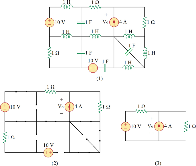
Solutions Of Problems Second Order And Higher Order Circuits Springerlink
Layer 2 refers to the data link layer of the network.
. Layer 3 diagrams are about subnets routing and the IP spaces. ZStack abstracts the networking model into L2 and L3 networks. In a network that includes many different types of cables such as fiber optic cables Category 567.
Layer 1 diagrams should show port numbers and indicate cable types. An L2 network provides a type of L2 isolation method while an L3 network basically represents. Ad Get the most powerful professional diagram software on the market.
An L3 network is a subnet created on an L2 network associated with network services. Ad Templates Tools Symbols For Easy Network Diagrams. Use Createlys easy online diagram editor to edit this diagram collaborate with others and export results to multiple.
This holds true even if all the hosts. Ad Get the most powerful professional diagram software on the market. This is how data moves across the physical links in your network.
There is one 1841 cisco router two 3560 cisco catalyst switches and 4 solaris sunfire T-1000 boxes. Is a powerful application which allows users to design local-area networks. Frank_Zhang 2018-05-10 1013.
WISP L2 Network Diagram classic by Issam Fayad. Network Diagram and Visio Layers 12 par Compte système le 27032016 1659. NetworMaps separates between physical L2 and logical L3 network diagrams which help in identifying the different elements connected on a network.
Lucidcharts network diagram software is quick easy to use. Endpoints 10101010 and 10101011 cannot communicate to endpoints 10202010 or 10202011 unless explicitly configured. Just share the network diagram with whoever you want to have access to it and he.
NetworkMaps lets more than one person to edit the same diagram at the same time. Ive been tasked with drawing a layer 2 network map of our very small datacenter network. The 3D diagram will be.
In this first article we show you how to take advantage of Visio layers to display different network. This network diagram shows a local area network LAN. The example of the network diagram below shows network architecture with configuration called two firewall demilitarized zone.
These are used when explaining a network to. FCPL L2 NETWORK DIAGRAM. Designers of the network as part of the analysis and design phase.
Lucidcharts network diagram software is quick easy to use. It shows the components that make up a network and how they interact including routers devices hubs firewalls etc. Use Createlys easy online diagram editor to edit this diagram collaborate with others and export results to.
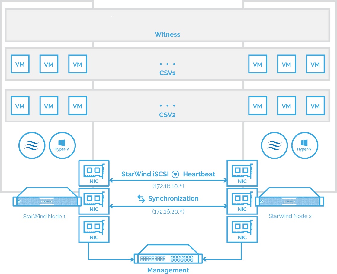
Build A 2 Node Hyper V Cluster With Starwind Virtual San Resource Library

Prepositions At In On For Time English Prepositions Learn English Prepositions
2
2
2

Client Tracking Options Cisco Meraki
A Complete Sophos Cyberoam Based Project Migration Implementation Upwork
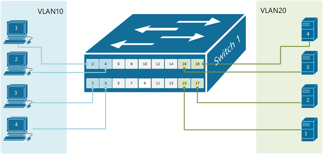
Forwarding Data Between Vlans Networkacademy Io
2
2
2
2

Magnetic Properties Of High Nuclearity Fex Oxo X 7 22 24 Clusters Analyzed By A Multipronged Experimental Computational And Magnetostructural Correlation Approach Inorganic Chemistry
What Is Meant By Inter Vlan Quora
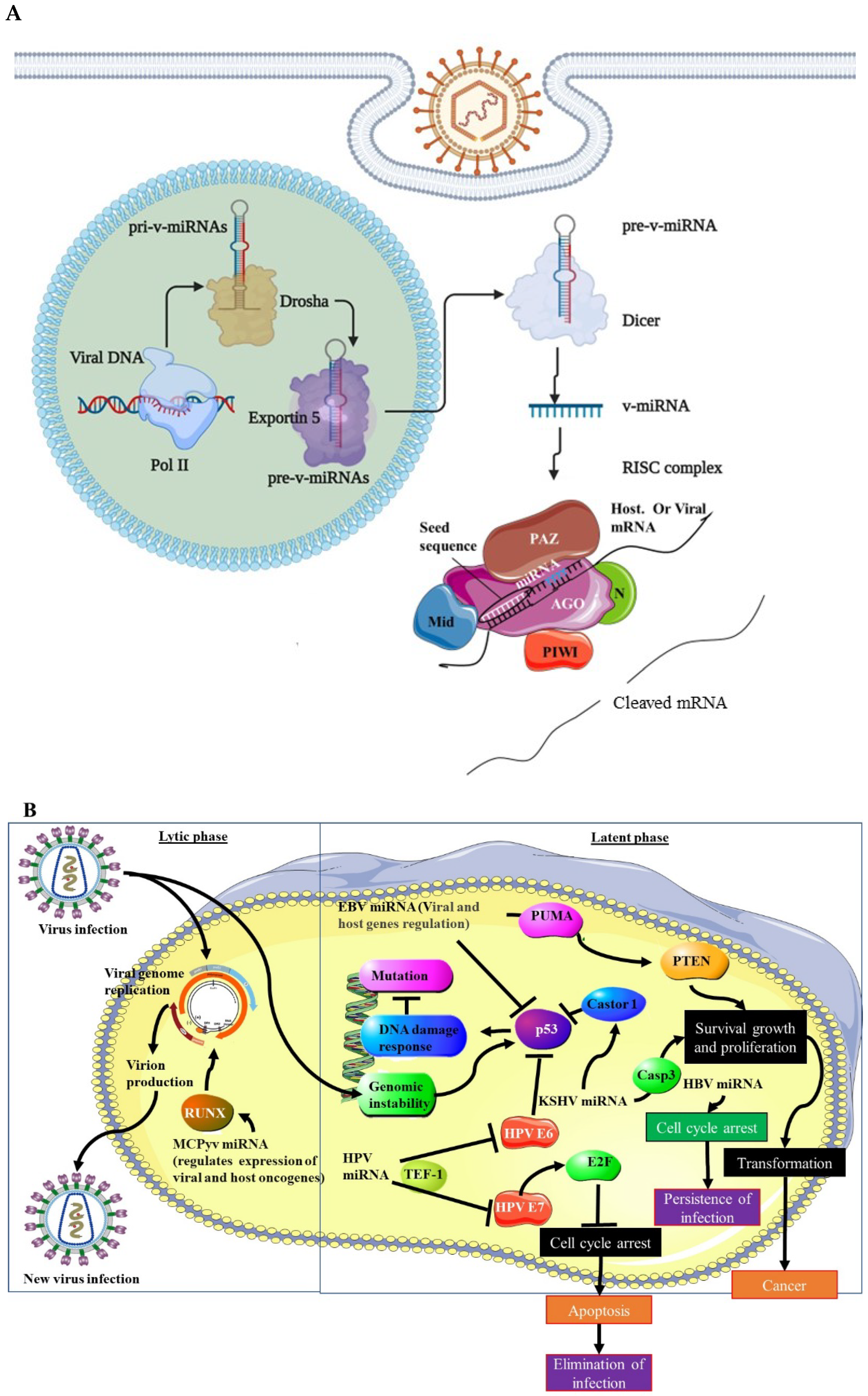
Microorganisms Free Full Text Viral Encoded Mirnas In Tumorigenesis Theranostic Opportunities In Precision Oncology Html
Blog The Art Of Network Engineering
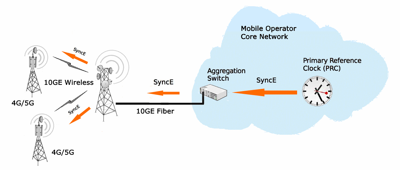
Elva 1 Has Implemented Synce And Poe In 10ge Ppc 10g Radios Millimeter Wave Components And Systems Waveguide Antennas Standard Gain Horns Mm Wave Radars Elva 1